









Laser Triangulation Solves New 3D Inspection Demands in AI Computing Era
As AI server components require micrometer precision, SinceVision utilizes advanced laser triangulation to overcome material reflectivity and multiple reflections during 3D inspection. By optimizing optical spot symmetry and preprocessing algorithms, these laser profilers deliver reliable geometric data for printed circuit boards, cooling plates, and BGA solder balls at kilohertz speeds. Presented at Industrial VISION Days 2026, hosted by VDMA in collaboration with VISION.



Executive Summary
As AI computing demand scales, the manufacturing of core AI server components requires advanced 3D inspection capabilities. Components like printed circuit boards, optical modules, and semiconductor packages face demanding assembly requirements. Laser triangulation solves these challenges by capturing X, Y, and Z data with micrometer accuracy at kilohertz speeds. Through optimized optics and algorithms, SinceVision 3D laser profilers overcome material reflectivity differences and multiple reflections to deliver reliable geometric data for AI hardware.
Watch the full presentation here: VISION 2026
The Evolving Demands of AI Server Inspection
The manufacturing and assembly of AI servers place tighter demands on core components. Components such as printed circuit boards, optical modules, and semiconductor packages face demanding manufacturing and assembly requirements.
Inspection needs to capture geometric information beyond X and Y positions. Today, manufacturers require 3D data including X, Y, and Z coordinates. Accuracy requirements have shifted from millimeters to micrometers, and speed requirements have increased to kilohertz levels. The practical objective is to obtain enough reliable 3D information to make an inspection decision within the available cycle time.
The Principles of Laser Triangulation
A laser projects a line onto the surface. A receiver then observes that line from an angle. A change in surface height shifts the image position on the sensor. After calibration, this image position is converted into a physical height. One laser line captures an X and Z profile, and motion in the Y direction builds the 3D surface.
Height comes from the position of the laser image, while brightness affects how reliably the system can locate that position. If the image becomes asymmetric, blurred, saturated, or mixed with additional reflections, the estimated line center can shift. Therefore, signal quality is central to accurate triangulation.
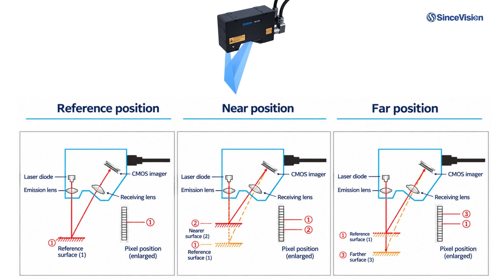
Image 1: Principal of laser triangulation
Challenge 1: PCB Resin Plugging
Resin filling helps prevent solder loss through vias and related joint defects.
Problem: Copper and resin produce very different return signals. A change in material can alter the captured intensity distribution. If that distribution becomes distorted or asymmetric, the estimated laser line center can move, even when the geometric height change is small.
Solution: The approach focuses on improving the symmetry of the native optical spot. We improve native on chip spot symmetry to reduce shifts in the detected line center. This reduces material dependent shifts in line center estimation, ensuring the measured profile more faithfully represents the surface geometry. We need to measure their relative surface heights without allowing material differences to dominate the result.
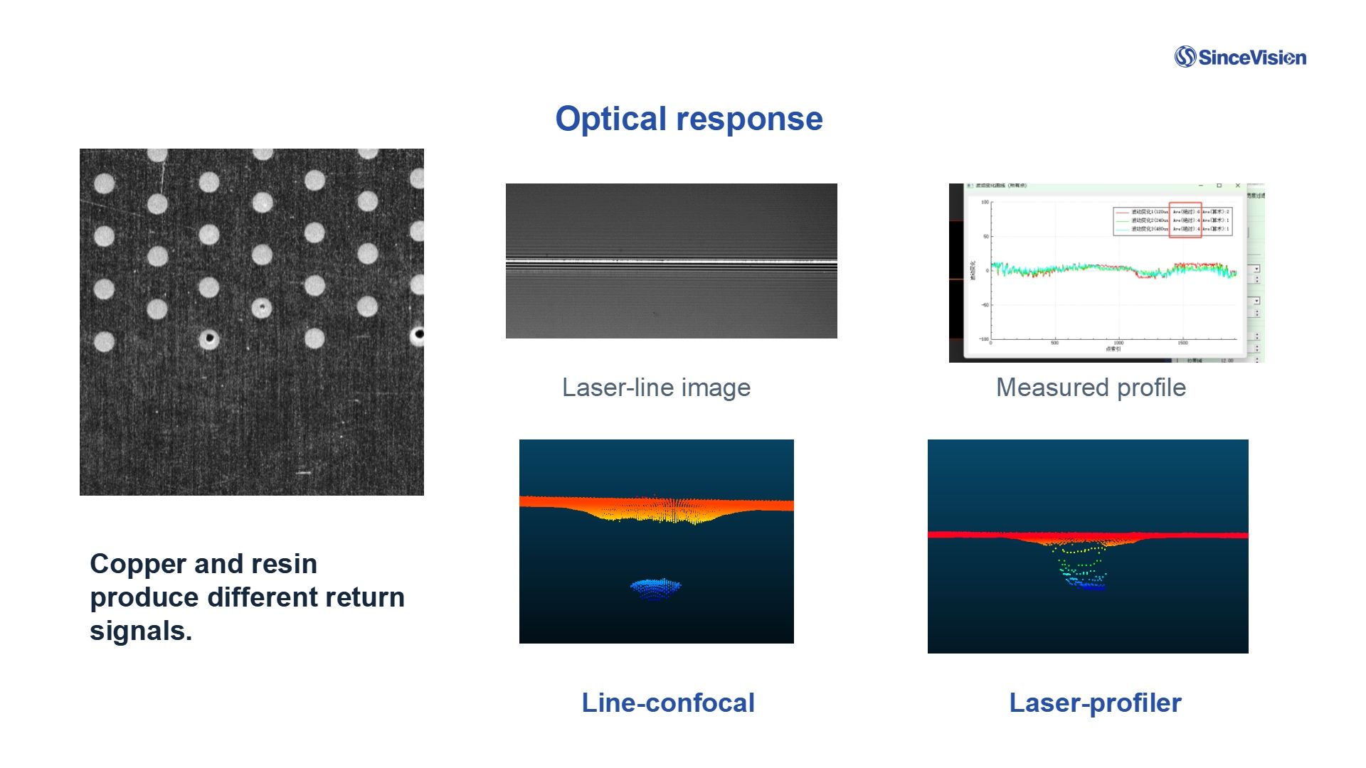
Image 2: PCB resin plugging
Challenge 2: Water Cooling Plate Inlets
Problem: The curved metal surface around an inlet can generate multiple reflections. Reflective metal edges create multiple reflections. In the raw intensity image, several bright traces can compete for a single height value. Choosing the brightest trace alone may select an unwanted reflection.
Solution: To recover the true surface contour, the processing works in stages.
First, we apply Gaussian preprocessing to reduce image noise.
Next, the algorithm segments candidate spots in each image column using intensity and gradient information.
Finally, the system selects reliable Z points by classifying strong and fallback candidates, and rejecting unsuitable reflections.
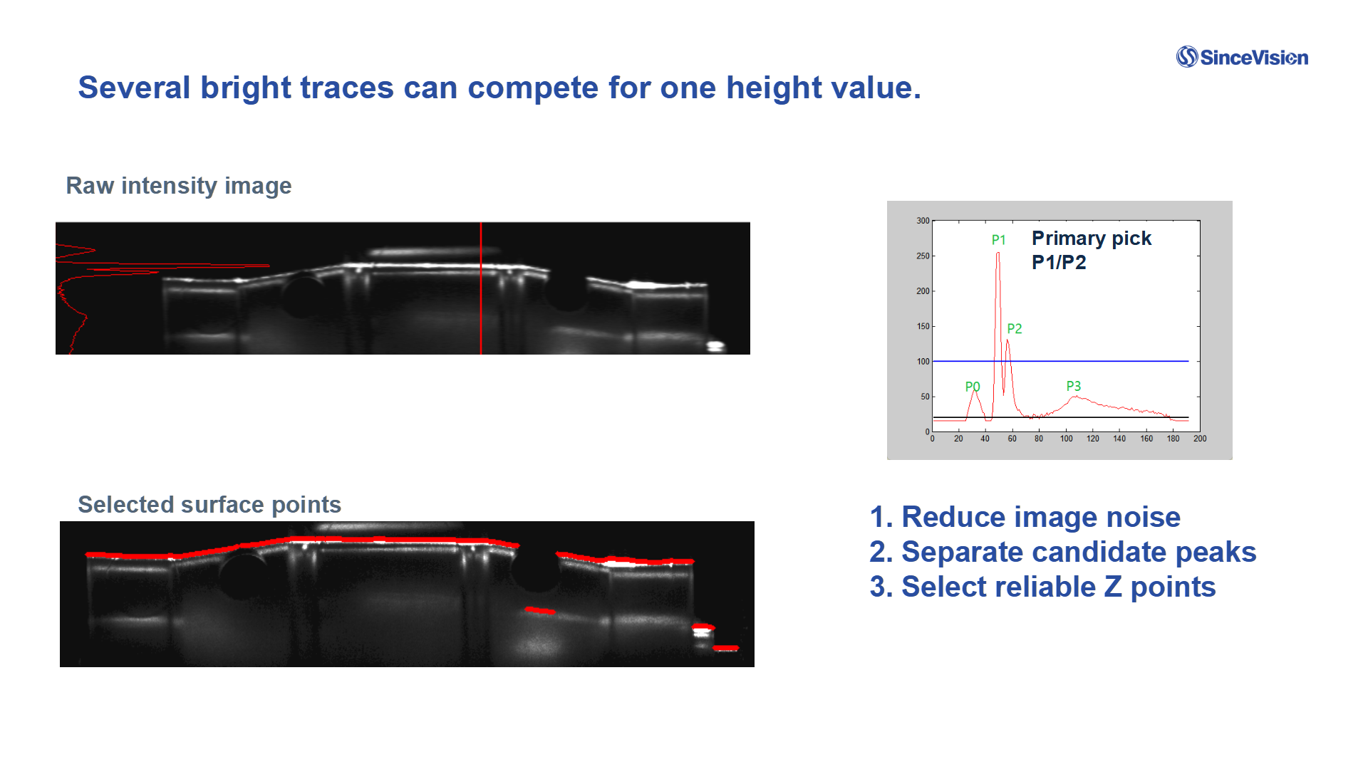
Image 3: Cooling-plate inlet
Challenge 3: Reflective BGA Inspection
Problem: Reflective solder balls complicate line detection. A solder ball is a small, curved, reflective surface. As the local surface angle changes, the direction and strength of the returned light also change, making parts of the profile difficult to capture.
Solution: This requires optimized optics for small, reflective features. The SR9520 laser profiler uses a laser line width of 25 micrometers and an X direction resolution of 2 micrometers. A large collection angle and efficient custom receiving optics capture useful returns. This approach offers a potential alternative to line confocal inspection for suitable, validated applications.
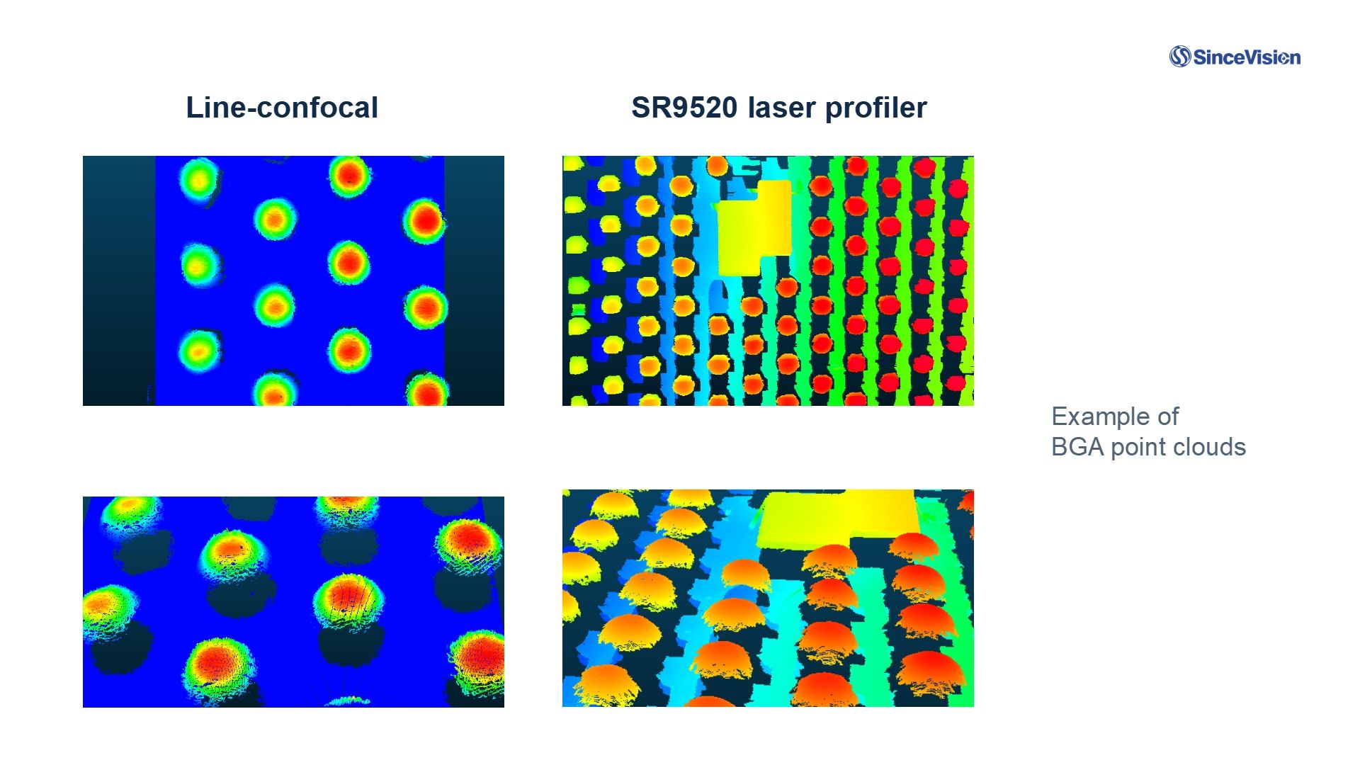
Image 4: Reflective BGA inspection
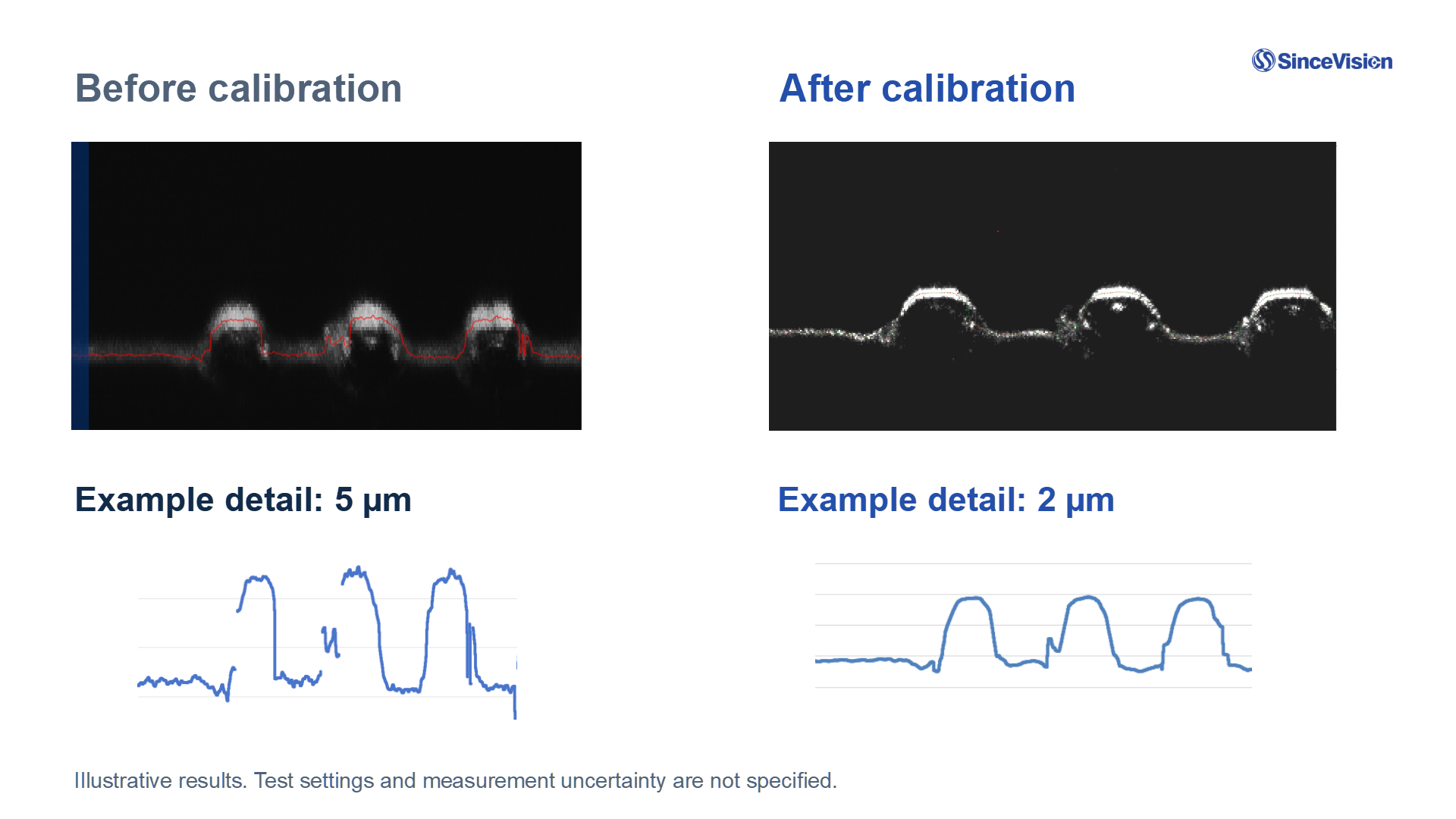
Image 5: BGA profiles calibration
Conclusion
Different signal problems call for different engineering responses. The common foundation is laser triangulation, supported by optical design, calibration, and application specific processing. The practical goal remains clear: obtain reliable geometric information at the speed the process requires.
About Author
Kevin Cheng is the Europe Sales Director at SinceVision, responsible for business growth and local team building across Europe. With a background in Electrical Engineering and nearly a decade of international experience in machine vision and industrial automation, he has worked across Asia, North America, and Europe. His expertise covers 3D laser profiling, high speed imaging, scientific imaging, precision measurement, and AI powered vision applications. Recognized for his technical leadership, he was a featured speaker at both Industrial VISION Days and Scientific VISION Days during VISION 2026 in Stuttgart, Germany, where he presented on solving 3D inspection bottlenecks for the AI computing era and new generation of low light imaging technology.
About SinceVision
Founded in 2014, SinceVision is a manufacturer of sensor technology. Specializing in the R&D, production, and provider of industrial sensors, high-speed imaging systems, & high-sensitivity cameras. With a global team of over 700 employees, SinceVision dedicates more than 60 percent of its staff directly to research and development. This deep engineering focus spans optics, FPGA processing, mechanical structure, and software, enabling SinceVision to push the boundaries of physical theory and solve the most complex 3D inspection bottlenecks in modern manufacturing.
Frequently Asked Questions
How does laser triangulation measure height?
A laser projects a line onto the surface, and a receiver observes that line from an angle. A change in surface height shifts the image position on the sensor. After calibration, this image position is converted into a physical height.
Why is PCB resin plugging difficult to inspect?
Copper and resin produce very different return signals. A change in material can alter the captured intensity distribution, causing the estimated laser line center to move. Improving native on chip spot symmetry helps reduce these shifts.
How do you inspect water cooling plates with multiple reflections?
Reflective metal edges create multiple reflections where several bright traces compete for one height value. Algorithms solve this by applying Gaussian preprocessing, segmenting peaks using intensity and gradient information, and selecting reliable Z points while rejecting unsuitable reflections.
Appendix: Full Presentation Transcript
The following is the unedited speech transcript of Kevin Cheng's presentation at Industrial VISION Days during VISION 2026 in Stuttgart, Germany.
Image 6: Kevin Cheng presenting at Industrial VISION Days 2026
Good morning everyone. Thank you all for joining me in this session today. My name is Kevin Cheng, I'm representing our company SinceVision. Today I will be talking about how laser triangulation solves new 3D inspection demands in AI computing Era, of core components in AI server manufacturing. I will talk about the problems we see, and how we solve it with our optimized optics and algorithms. So Let's begin.
Before we dive in on the technical side, please allow me to introduce SinceVision. SinceVision was founded in 2014, with a strong background in industrial vision and inspections. We are now an industry leader in industry imaging and sensor, especially for 3D laser profiler. Now company have over 700 members, over 60% is RD engineers. We like to keep innovate on technology, and pushing it to edges of physical theory.
The Basic Principle of Laser Triangulation
Let us start with the basic principle. A laser projects a line onto the surface. A receiver observes that line from an angle. When the surface height changes, the illuminated point appears at a different position on the image sensor. After calibration, we can convert that image position into a physical height. The illustration shows one cross section. A line laser performs this measurement across many positions along the X direction, producing an X Z profile. As the part or sensor moves in the Y direction, successive profiles build a three dimensional surface.
There is an important distinction here: height comes from the position of the laser image. Brightness affects how reliably we can locate that position. If the image becomes asymmetric, blurred, saturated, or mixed with additional reflections, the estimated line center can shift. That is why signal quality is central to accurate triangulation.
3D Inspection Demands in AI Hardware
Why are these capabilities increasingly relevant to AI hardware? Components such as PCBs, optical modules, and semiconductor packages face demanding manufacturing and assembly requirements. Inspection needs to capture geometric information beyond X Y position. Depending on the component, we may need to measure step height, surface shape, or coplanarity. At the same time, small geometric deviations must be resolved on surfaces with very different optical behavior. These measurements also need to fit within the production cycle.
A high profile rate is useful, but the actual inspection speed depends on exposure, scan spacing, required coverage, and data processing. The practical objective is therefore to obtain enough reliable 3D information to make the inspection decision within the available cycle time. The following examples show how that objective translates into specific engineering problems.
This slide summarizes the three applications. For PCB resin filling, copper and resin can produce very different return signals. We need to measure their relative surface heights without allowing material differences to dominate the result. For cooling plates, the curved metal surface around an inlet can generate multiple reflections. Several candidate signals may appear, and the system must identify the one corresponding to the actual surface. For BGA inspection, reflective solder balls combine small geometric features with strong directional reflections. We need sufficient detail to evaluate their shape and height. These are different failure mechanisms. Understanding which mechanism affects the measurement allows us to choose the appropriate optical design or processing strategy.
PCB Resin Filling Application
Let us begin with the mixed material PCB application. In this sample, the copper surface produces a weaker return, while the resin produces a stronger return. The inspection task is to evaluate the resin fill height relative to the surrounding copper surface. The difficulty is that a change in material can alter the captured intensity distribution. If that distribution becomes distorted or asymmetric, the estimated laser line center can move, even when the geometric height change is small.
Our approach focuses on improving the symmetry of the native optical spot. The aim is to reduce material dependent shifts in line center estimation, so that the measured profile more faithfully represents the surface geometry. The images show the sample, the laser line image, and example measurement results. The lower comparisons are qualitative illustrations. The key point is that optical spot quality directly influences how consistently we can measure across a material boundary.
Water Cooling Plate Inlets Application
The second application involves the inlet profile of a cooling plate. Here, the problem is multiple reflections. In the raw image, several bright traces can compete for a single height value. Choosing the brightest trace alone may select an unwanted reflection. The processing therefore works in stages.
First, Gaussian preprocessing reduces image noise. Next, the algorithm separates candidate spots in each image column using intensity and gradient information. It then classifies stronger and fallback candidates and rejects signals that do not meet the selection criteria. The supplied example uses high and low thresholds together with gradient evidence. The red points in the lower image show the selected surface profile. This case demonstrates why candidate selection matters: reliable Z data requires deciding which optical signal actually represents the surface we want to measure.
BGA Solder Ball Inspection Application
The third application is BGA inspection. A solder ball is a small, curved, reflective surface. As the local surface angle changes, the direction and strength of the returned light also change. This can make parts of the profile difficult to capture. The SR9520 design described here combines a large collection angle with efficient custom receiving optics. It also uses a laser line width of 25 micrometres and an X direction resolution of 2 micrometres.
These specifications describe different aspects of the system. Laser line width relates to illumination, while X direction resolution describes lateral measurement detail. Neither figure should be interpreted as Z direction accuracy. The point clouds illustrate the type of BGA surface information available for inspection. For suitable, validated applications, this approach offers a potential alternative to line confocal inspection.
This slide brings the discussion back to the captured signal. The upper images show the laser line profiles, and the lower images show the extracted contours. The original examples identify 2 micrometre and 5 micrometre detail respectively. When reviewing these images, we look at the definition of the line, the continuity of the profile, and the preservation of small surface features. This is an illustrative comparison. Matched test conditions and measurement uncertainty are not documented here, so the images do not establish a universal accuracy ranking.
For BGA coplanarity, the eventual task is to measure ball top heights relative to a defined reference plane. A production evaluation should therefore compare the same sample under controlled settings and verify both the measurement result and the required cycle time. That connects visible profile detail with an actual manufacturing acceptance decision.
To conclude, the three applications show how different signal problems call for different engineering responses. For PCB resin filling, improving spot symmetry helps reduce localization bias across materials. For cooling plate inlets, candidate selection helps reject unwanted reflections and recover the surface contour. For BGA inspection, fine lateral resolution and efficient receiving optics support detailed surface measurement. The common foundation is laser triangulation, supported by optical design, calibration, and application specific processing.
As AI hardware manufacturing continues to evolve, the practical goal remains clear: obtain reliable geometric information at the speed the process requires. Thank you for your attention. I would be happy to discuss your components, surface conditions, and inspection requirements.

Featured Sensors


SRI8060

SRI7060

SRI7140
You can also read
How 3D Line Laser Profilers Solve Critical Challenges in Automotive Tire Manufacturing
Nov 09, 2026
Unlocking Flame Cellular Instability: Advanced High-Speed Camera Flame Imaging with the SinceVision SH8 Series
Oct 09, 2026
Analyzing Brittle Fracture in Tomato Roots: A SinceVision High-Speed Camera & DIC Experiment for Agricultural Robotics
Sep 01, 2026
3D Laser Profiler for Lithium-Ion Battery Top Cover Bonding Height Measurement
Aug 14, 2026
Observation of Embryonic Fibroblasts with sCMOS Camera for Multichannel Imaging
Jun 23, 2026



 Compare
 Clear the comparison bar

