










High-Speed Imaging: Engineering Principles, Optical Trade-Offs, and R&D Applications
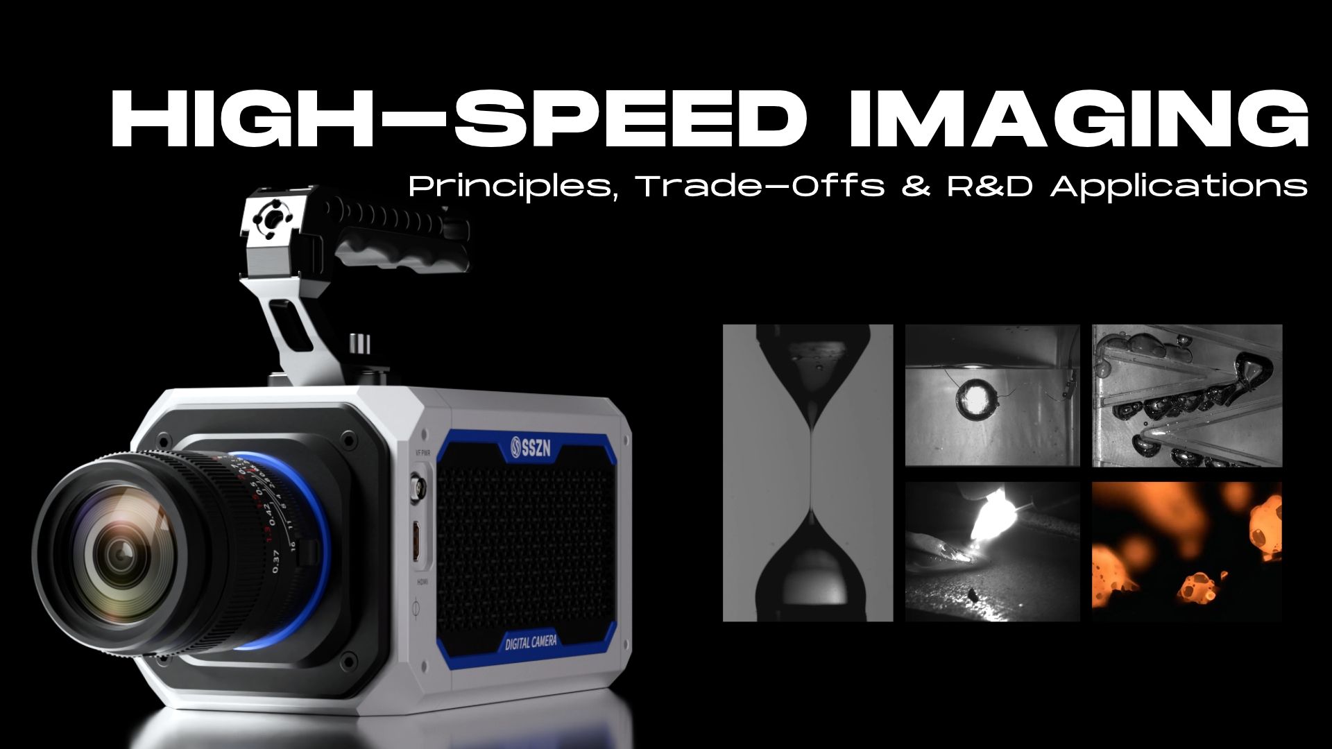
High-speed imaging is a quantitative optical diagnostic technique that records transient physical events at frame rates from 250 fps to over 1,000,000 fps using global shutter CMOS sensors, high-intensity flicker-free illumination, and onboard RAM ring buffers. By pairing microsecond-scale image sequences with analytical methods like Digital Image Correlation (DIC), Particle Image Velocimetry (PIV), and Schlieren optics, R&D engineers measure structural strain, fluid velocity, combustion propagation, and battery failure across industrial and scientific laboratories.


1. Executive Summary
High-speed imaging is a quantitative optical measurement technique that captures rapid, transient physical events at frame rates exceeding 250 frames per second (fps), scaling from 1,000 fps in industrial diagnostics to over 1,000,000 fps in scientific research. By recording microsecond-scale phenomena and playing them back in slow motion, high-speed video analysis reveals mechanical deformation, fluid dynamics, and thermal reactions invisible to the human eye or standard 30 to 60 fps cameras.
Unlike consumer slow-motion video created for visual entertainment, quantitative R&D high-speed imaging prioritizes geometric accuracy, linear radiometric response, and precise time synchronization. Researchers use calibrated high-speed photography to extract exact velocity vectors, structural strain fields, and failure thresholds from every recorded frame.
2. How High-Speed Imaging Works: The Core Engineering Trade-Offs
Originating in 1878 with Eadweard Muybridge's sequential motion studies of galloping horses, modern high-speed imaging relies on specialized CMOS sensors, high-bandwidth memory, and intense illumination. Designing an effective test setup requires balancing three interconnected physical limits.
Frame Rate vs. Spatial Resolution
Every CMOS image sensor has a maximum pixel readout bandwidth, typically measured in gigapixels per second (GP/s). Because total data throughput is fixed for a given sensor architecture, increasing the frame rate requires reducing the active pixel count per frame:
Full-Frame Capture: At 1,000 to 2,000 fps, sensors generally maintain full megapixel resolution (such as 1920×1080 or 1280×1024) to preserve wide fields of view.
Region of Interest (ROI) Cropping: Pushing capture speeds to 50,000 fps or 100,000 fps requires cropping the active sensor array to a narrow strip (such as 512×256 or 256×128 pixels). Engineers must balance spatiotemporal resolution so the target remains large enough in pixels to measure accurately.

Exposure Time and Illumination ("The Limiting Reagent")
In high-speed imaging, available light is almost always the primary constraint. Frame rate sets the maximum time window between frames, while exposure time (shutter speed) must be even shorter to freeze fast-moving subjects without motion blur.
At 10,000 fps, the total frame interval is 100 microseconds (μs). To prevent a projectile moving at 100 m/s from blurring across multiple pixels, the exposure time may need to drop to 1 to 5 μs. Standard workshop AC lighting (50 Hz or 60 Hz) creates severe brightness flicker and dark banding at these shutter speeds. Reliable transient event capture requires high-intensity, flicker-free DC LED arrays, pulsed xenon strobes, or synchronized laser illumination paired with a CMOS global shutter. Unlike a rolling shutter that scans line by line and warps rotating blades or speeding projectiles, a global shutter exposes all pixels simultaneously to preserve true spatial geometry.
Data Throughput and Triggering
Recording uncompressed 10-bit or 12-bit monochrome or color frames at 10,000 fps generates several gigabytes of data per second (often 5 to 20 GB/s), far exceeding standard hard drive write speeds. High-speed systems solve this by streaming frames into a continuous onboard RAM ring buffer. Because unpredictable events (such as a sudden structural fracture or electrical arc) are difficult to time manually, researchers use hardware TTL triggers, acoustic sensors, or image-based motion triggers to freeze the ring buffer before and after the exact instant of interest.
3. Eight Key R&D and Industrial Applications of High-Speed Imaging
High-speed imaging serves as a foundational diagnostic tool across eight primary engineering and scientific sectors.
| Sector | Key Test Scenarios | Typical Frame Rate Range | Primary Engineering Insight Gained |
Automotive Safety | Seat crash tests, airbag deployment, windshield impact, trolley collisions | 1,000 to 10,000 fps | Kinematics of occupant protection, glass fracture patterns, and structural deceleration |
Lithium Battery & New Energy | Cell winding, nail penetration, laser welding spatter, drop testing | 2,000 to 50,000 fps | Winding fault detection, thermal runaway venting velocity, and weld keyhole stability |
Semiconductor | Electronic component sorting, precision chip-picking trajectories | 1,000 to 5,000 fps | Pick-and-place vibration damping, nozzle alignment, and micro-bounce elimination |
Fluid Mechanics | Droplet coalescence, underwater cavitation, water-oil mixing, microfluidics | 5,000 to 200,000+ fps | Bubble collapse shockwaves, interfacial tension, and microchannel flow velocity |
Life Sciences | Bird flight takeoff, microchannel heat dissipation, bacterial flagella motion | 1,000 to 20,000 fps | Aerodynamic lift mechanics, boiling nucleation dynamics, and cellular propulsion |
Biomimetics & Medical | Bio-inspired wing flapping (DIC), modal vibration, medical device motion | 1,000 to 10,000 fps | Full-field surface strain gradients, structural resonance modes, and actuator timing |
Combustion & Propulsion | Droplet ignition, water mist extinguishing, flame stability, rocket plumes | 5,000 to 100,000+ fps | Flame front propagation speed, exhaust turbulence, and mist cooling kinetics |
Pharmaceutical | Vial aluminum cap crimping and sealing inspection | 1,000 to 3,000 fps | High-throughput mechanical seal verification and stopper compression consistency |
Automotive Safety Testing
In automotive crash test imaging, onboard and trackside systems record vehicle seat crash safety testing, occupant protection system deployment (airbags and seatbelt pretensioners), windshield impact testing, and trolley collision testing. Recording at 1,000 to 10,000 fps lets safety engineers measure millisecond-level dummy kinematics and structural crush zones without motion blur.

Image 1: Car Seat Crash Testing
Lithium Battery and New Energy Manufacturing
Battery R&D and production lines rely on high-speed video analysis to inspect lithium cell winding and pinpoint winding faults before cell assembly. During destructive safety qualification, high-speed cameras document battery acupuncture (nail penetration) tests and lithium battery drop testing to quantify thermal runaway venting. In manufacturing, researchers also capture laser welding keyhole dynamics and laser welding spatter observation to stabilize busbar and tab joints.
Semiconductor Manufacturing
Modern die bonders and sorters move thousands of components per hour. High-speed imaging verifies semiconductor electronic component sorting and the semiconductor chip-picking process, exposing micron-scale tool vibration, vacuum tip bounce, and die misalignment that limit yield.
Fluid Mechanics and Microfluidics
Fluids deform rapidly at small scales. Researchers deploy high-speed photography to capture the droplet coalescence process, liquid solution extensibility, and water-oil mixing dynamics. In high-energy and micro-scale studies, cameras resolve cavitation bubble observation, cavitation phenomena generated by underwater discharge, and laminar or turbulent fluid flow in microfluidic chips.
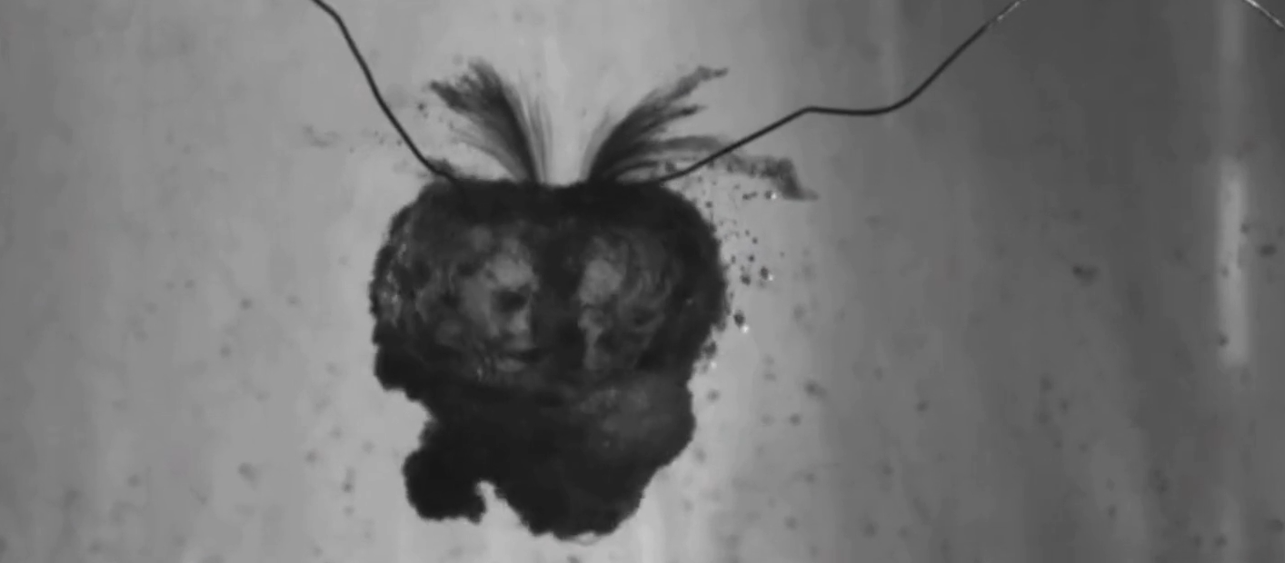
Image 2: Observing Cavitation Phenomena Generated by Underwater Discharge
Life Sciences and Bio-Transport
Biological motion often exceeds standard video limits. High-speed setups capture pigeon takeoff to reveal the hidden mechanics of bird flight, track microscopic bacterial flagella movement under high-magnification optics, and visualize two-phase boiling during the microchannel heat dissipation process.
Biomimetics and Medical Mechanics
When designing bio-inspired robots or surgical instruments, engineers pair high-speed imaging with Digital Image Correlation (DIC) for biomimetic wing flapping analysis and vibration modal testing for bio-inspired wings. In healthcare R&D, motion trajectory analysis of medical mechanical action verifies injector spring release, catheter deployment, and micro-valve actuation.
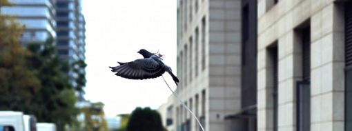
Image 3: Pigeon Takeoff
Pharmaceutical Packaging
Automated fill-finish lines operate continuously at hundreds of units per minute. High-speed imaging assists in observing the sealing process of pharmaceutical vial aluminum caps, catching misaligned crimping rollers or elastomer stopper rebounds before compromised vials reach distribution.
Combustion and Propulsion
Studying reactive flows requires isolating bright flame fronts from background turbulence. Researchers use high-speed imaging for observation of special material combustion, single droplet combustion experiments (tracking how fuel droplets ignite, expand, and burn), steady-state flame profile observation, ignition tube tests and flame propagation, water mist fire extinguishing dynamics, and rocket plume and exhaust analysis.
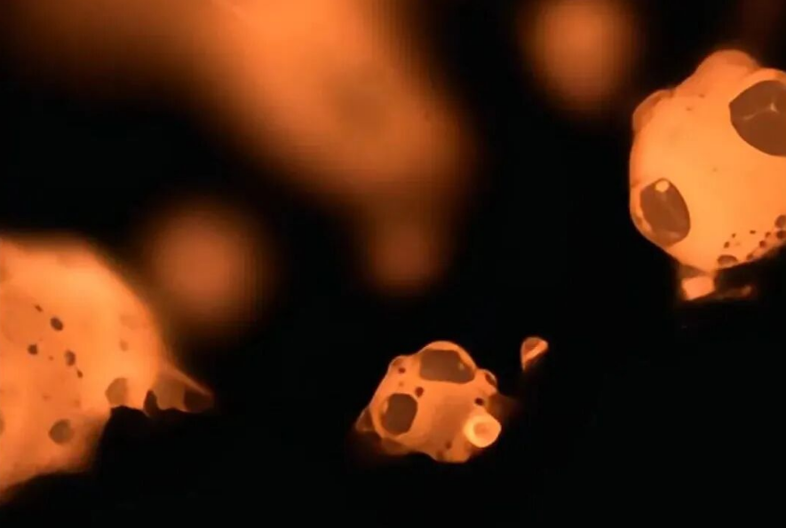
Image 4: Observation of Special Material Combustion
4. Integrating High-Speed Imaging with Quantitative Analysis
Raw slow-motion playback provides qualitative insight, but R&D laboratories extract deeper value by coupling high-speed image sequences with specialized optical metrology algorithms:
Digital Image Correlation (DIC): By applying a random high-contrast speckle pattern to a test specimen, DIC software tracks subset displacements across thousands of frames to compute full-field surface strain, crack propagation, and structural deformation without contact gauges.
Particle Image Velocimetry (PIV): Seeding a liquid or gas flow with microscopic tracer particles and illuminating them with a pulsed laser sheet allows high-speed imaging to map instantaneous 2D or 3D fluid velocity vectors.
Schlieren and Shadowgraph Optics: Pairing a high-speed sensor with collimated mirrors visualizes refractive index gradients in transparent air, capturing supersonic shockwaves, rocket exhaust plumes, and thermal convection currents.
High-Speed Infrared Imaging: Replacing visible-light CMOS sensors with cooled infrared detectors (InSb or MCT) captures microsecond thermal transients during laser welding, brake friction, or battery thermal runaway.
5. Practical Checklist: Designing a High-Speed Imaging Test Setup
Follow these five steps when configuring a laboratory or industrial test bench:
Define Event Duration and Temporal Resolution: Estimate the total event window (in milliseconds) and the fastest feature velocity. Select a frame rate high enough to capture at least 20 to 50 frames across the critical transition.
Calculate Field of View and Pixel Resolution: Confirm that the target ROI resolution at your chosen frame rate provides enough pixels across the smallest feature of interest (for example, at least 3 to 5 pixels per speckle dot for DIC).
Select Continuous DC or Pulsed Illumination: Match light intensity to your shortest required exposure time. Use flicker-free DC LEDs for continuous runs or synchronized pulsed lasers for intense combustion and welding tests.
Configure Hardware Triggering: Set pre-trigger and post-trigger memory allocations in the RAM ring buffer so the camera captures the baseline state right before impact, ignition, or fracture.
Calibrate Optical Distortion and Scale: Capture a precision calibration grid in the target focal plane before running the test to convert raw pixel shifts into exact millimeters and meters per second.
6. Frequently Asked Questions (FAQ)
What qualifies as high-speed imaging versus standard slow-motion video?
High-speed imaging is defined by recording frame rates above 250 fps, scaling into tens of thousands or millions of frames per second for scientific and industrial analysis. Standard consumer slow-motion video typically records at 120 to 240 fps with heavy video compression, whereas quantitative high-speed imaging preserves uncompressed raw frames for accurate spatial and temporal measurement.
Why does image brightness drop so sharply when increasing frame rates?
As the frame rate increases, the maximum available time to expose each frame shrinks proportionally (for example, 100 μs at 10,000 fps versus 16,667 μs at 60 fps). Because fewer photons hit the sensor during each microsecond exposure, image brightness drops dramatically unless compensated by high-output, flicker-free illumination and fast-aperture lenses.
What are the downsides of using an ultra-fast shutter speed in high-speed imaging?
An ultra-fast shutter speed eliminates motion blur on rapid targets, but it severely limits photon collection. This forces engineers to either increase artificial light intensity (which can heat sensitive biological or polymer samples) or increase sensor gain, which introduces electronic noise and reduces dynamic range.
How do engineers choose between global shutter and rolling shutter for fast-moving targets?
R&D engineers almost exclusively use CMOS global shutter sensors for high-speed imaging because every pixel exposes simultaneously at the exact same instant. Rolling shutters read out pixel rows sequentially, which causes severe geometric skewing ("jello effect") on rotating fan blades, vibrating wings, and high-velocity projectiles.
How does high-speed infrared imaging differ from visible-light high-speed imaging?
Visible-light high-speed imaging measures reflected photons (400 to 700 nm) to track physical geometry, cracks, and motion. High-speed infrared imaging uses specialized thermal sensors (such as 3 to 5 μm MWIR detectors) to measure emitted heat radiation at kilohertz frame rates, revealing rapid temperature spikes in combustion, electronics, and thermal runaway events.
Featured Cameras
SH8-120
SH6-505
SH3-105
SH2-202

SHS-202
You can also read
High-Speed Imaging: Engineering Principles, Optical Trade-Offs, and R&D Applications
Nov 12, 2026
Laser Triangulation Solves New 3D Inspection Demands in AI Computing Era
Nov 10, 2026
How 3D Line Laser Profilers Solve Critical Challenges in Automotive Tire Manufacturing
Nov 09, 2026
3D Laser Profiler Inspection for AI Server High-Speed Connectors and Chassis Assemblies
Oct 29, 2026
Unlocking Flame Cellular Instability: Advanced High-Speed Camera Flame Imaging with the SinceVision SH8 Series
Oct 09, 2026



 Compare
 Clear the comparison bar

